Cooling Device for Electrical Equipment
Pertinent ArtThis invention relates, to the instrument and electrical engineering, but more specifically as a cooling device for electrical equipment, which can be used for cooling the units of different electronic devices, such as cooling the CPUs of computers, laptops, graphics cards processors and their components, power supply units for electrical equipment, as well as cooling other electrical devices intended for different applications, such as movie projectors, TV cameras, voltage stabilizers, transformers, different converters, rectifiers, etc.
State of the ArtIn most of the known existing cooling systems for electrical equipment and electronic equipment such as computers the heat is carried out from its sources in three stages.
The first stage is transferring heat from the heat source to the heat-conducting element by thermal conductivity. We consider as the heat-conducting element any high-tech device for transferring heat a short distance (heat pipes, water systems, metals with high thermal conductivity rate, etc.). In this case, the heat source is thermally connected to the hot end of heat-conducting element.
The second stage is transferring heat from heat source to the radiator by means of heat-conducting elements. In this case, the radiator is thermally connected to the cold end of heat-conducting element.
The third stage is transferring heat from the radiator to the air by convection. At this stage, the system can use natural convection for removal of small amounts of heat as well as forced convection under high thermal loads.
For example, we know a cooling device for computers that increases convective component of heat transfer by installing over the heat source, which is tied in with heat-conductive base, a cooling device with an axial fan, which blows air over a heat-conducting base and, consequently, over the heat source. On the opposite sides of the fan are two radiators, with cooling fins, cooled by the air from the same fan. These radiators are tied in with heat-conductive base by heat pipes (US 2006/0164808 A1, IPC H05K 7/20 (2006.01), 2006).
We know a computer CPUs cooling device includes two radiators with fins, connected by heat pipes to the cooling device's heat-conductive base which is tied in to the heat source. The heat-conductive base is built for cooling by using the Peltier effect and its two parts are thermally connected with two aforementioned radiators. The axial fan in this known set-up, blows air along the fins of both radiators (US 7,331,185 B2, IPC F25B 21/02 (2006.01), 2008).
Also a device for cooling power electronics uses a diametrical fan with air coming from the output vent of its body, directionally blown along the fins of the radiator, which is tied in to the heat source (DE 36 09 037 A1, IPC H05K 5/02, 1986).
Thus, at the existing stage of development, as illustrated by known designs described above, the cooling systems primarily transfer the heat from radiator to the air by convection.
However, the process of such heat transfer in the known designs from the radiator to the air by convection, though activated by blowing air over heat transfer surface, is the least optimized from heat engineering point of view and meets maximum thermal resistance in the cooling device. Instead of intensifying heat transfer, most manufacturers of cooling systems head toward increasing radiator unit sizes and fan speeds. This ultimately leads to increasing the weight of heat transfer device and its cost, as well as to appearance of annoying acoustic noise.
Substance of InventionThe objective of this invention is to intensify the convective component of heat transfer, which ultimately leads to increasing the energy efficiency of heat transfer device, reducing its weight and cost.
This objective is achieved through solution that provides the cooling device for electrical equipment which includes:
- At least one fan with directional air output vent from the body,
- at least one vortex chamber with at least one air input vent to ensure air twist in the chamber connected to the air output vent from the fan body, and with a vent for the air output on at least one end,
- at least one heat-conducting element located in the inner volume of the vortex chamber and implemented with the option to interact with at least one electrical equipment element, located outside the vortex chamber, for its cooling.
The heat-conducting element can be implemented in the form of heat pipe either in the form of a rod from the heat-conducting material. Its outer surface can be augmented with a relief pattern such as finning to increase the area of heat transfer and intensify heat transfer process.
Typically, the heat-conducting element is placed in the vortex chamber longitudinally, at a distance from the axis of the vortex chamber that is larger than the radius of air output vent at the end of the vortex chamber.
One possible option is to provide cooling device with four heat-conducting elements placed in the vortex chamber longitudinally, at a distance from the axis of the vortex chamber, with a larger radius of air output vent at the end of the vortex chamber.
To ensure the liquid cooling, the heat-conducting element can be implemented in the form of a pipe that allows the coolant to pass through it.
The possible options to implement the invention include providing the vortex chamber with tangential or spiral input vent.
As an option, the vortex chamber can be made from heat-conducting material. In that case, one possible option includes providing the vortex chamber with a set of heat-conducting elements thermally connected to the body of the vortex chamber or made as a one piece with it, which corresponds to the case, when the body of the vortex chamber is made with a base to ensure the contact with electrical equipment component for its cooling. In such case, it is also possible to make the body of the vortex chamber with the elements of the relief on the outside to increase the area of heat transfer.
It is possible when the cooling device includes heat-conductive base implemented with an option to tie in with an electric equipment element for its cooling. In such case, the heat-conducting element is connected on the outside vortex chamber with the heat-conductive base.
As an option, the heat-conductive base may be located opposite the air output vent of the vortex chamber. In such case, the heat-conductive base may be implemented as a heat-dissipating radiator with its heat-dissipating area located opposite the air output vent of the vortex chamber. One possible option in this case will be to make the vortex chamber with a nozzle fixed from outside and connected with its inner volume through the air output vent at the end of the vortex chamber while the end of the nozzle is directed at the heat-conductive base.
The inner volume of the vortex chamber can be made in its cross-section in a cylindrical, elliptical or multi-faceted form.
As an option, the invention may be implemented with two fans in the cooling device and the body of the vortex chamber made with two air input vents arranged symmetrically to the axis to ensure air twist in the vortex chamber, and in such case each air input vent is tied in with air output vent from the body of a separate fan.
As an option, the invention may be implemented with two reflection-symmetric vortex chambers in the cooling device mounted so that their bodies are tied in with each other and with unidirectional arrangement of air input vents to ensure air twist in the chamber and connected to the air output vent from the body of one of the fans.
As an option, the invention may be implemented with two pairs of reflection-symmetric vortex chambers in the cooling device mounted in each pair so that their bodies are tied in with each other in the area of air input vents, which ensure air twist in the chamber, and with unidirectional arrangement that have their air input vents connected to the air output vent from the body of one of the fans.
Description of Graphic Materials Illustrating the Invention Fig. 1 and Fig. 2 represent the diagrams of the cooling device for electrical equipment graphically illustrating the principle of its work; views of the vortex chamber, respectively, the side view and the view by the end of vortex chamber. Fig. 3 and Fig. 4 show schematically the design of the cooling device with a vertical layout intended for cooling the processor that includes a vortex chamber with two fans which corresponds to the diagrams shown in Fig. 1 and Fig. 2.
Fig. 5 shows the layout of a standard computer system unit with the mounted cooling device with a vertical layout intended for cooling the CPU.
Fig. 6 and Fig. 7 represent vertical layout option of the cooling device with finned heat-conducting elements thermally connected to the heat-conducting base, which is tied in with heat source and cooled by the air flow coming out of the chamber.
Fig. 8, Fig. 9 and Fig. 10 represent horizontal layout option of the cooling device with the axis of vortex chamber positioned in parallel to the mounting surface plane, with one diametrical fan and nozzle directing the air from vortex chamber to the heat-conducting base.
Fig. 11 represents the cooling device with horizontal layout, which has its vortex chamber made from heat-conducting material and is directly and thermally connected to the heat source through a heat-conducting base.
Fig. 12, Fig. 13 and Fig.14 show an example of a low-profile layout for the cooling device with one vortex chamber that has tangential air input vent connected to one centrifugal fan.
Fig. 15 represents similar construction with a spiral air input vent to the vortex chamber.
Fig. 16 shows an example of low-profile cooling device implementation that includes two reflection-symmetric vortex chambers connected to one centrifugal fan.
Fig. 17 shows an example of low-profile cooling device implementation that includes two pairs of reflection-symmetric vortex chambers connected to one centrifugal fan.
Fig.18 and Fig.19 represent cooling device implemented for the liquid cooling system of electrical piece of equipment.
Fig.20 shows the layout of a standard computer system unit with liquid cooling system implemented via the use of cooling device represented in Fig. 18 and Fig.19.
Fig.21 and Fig.22 show an example of a low-profile structural implementation of a cooling device located on the graphics card with heat-conducting element made in the form of vapor chamber, which will be explained below.
Fig.23 shows an example of a low-profile structural implementation of a cooling device located on the graphics card with the heat-conducting element made in the form of vapor tower, which will be also explained below.
Fig.24 and Fig.25 represent cooling device with horizontal layout with heat-conducting element made in the form of vapor chamber with fins.
Fig.26 shows the distribution of temperature fields in the cross section of simulated cooling device.
Detailed Description of Invention Implementation Examples
The cooling device for electrical equipment implemented in accordance with the present invention operates under the principle illustrated in the diagrams shown in Fig. 1 and Fig. 2. In the example corresponding to these diagrams (Fig. 3 and Fig. 4), the cooling device for electrical equipment includes a vortex chamber 1 with two air input vents 2 and 3 located so that they can ensure the air twist in the inner volume 4 (Fig.1) of the vortex chamber. The vortex chamber 1 is connected by specified air input vents 2 and 3 to directional air output vents 5 and 6 (Fig.4) from the bodies of two diametrical fans 7 and 8 (Fig.4; not shown in the diagrams in Fig.1, Fig.2 and Fig.3) with impellers 9. The air output vents 10 and 11 (Fig.1 and Fig.3) are implemented on the ends of vortex chamber 1.
Four heat-conducting elements 12 are mounted longitudinally in the inner volume of the vortex chamber and each of heat-conducting elements is made with an area 13 exposed outward (by the hot end) (Fig.1 and Fig.3) to interact (thermally connect) with one or more pieces of electrical equipment for their cooling, and in this specific case with surface 14 of the CPU 15 (Fig.3). Heat-conducting elements 12 are located at a distance from the axis of the vortex chamber 1 that is larger than the radius of vents 10 and 11.
In accordance with patent claims, vortex chamber 1 can include only one air input vent 2 or 3, one fan 7 or 8 and a vent only at one end (10 or 11), which will be further illustrated in the examples below.
There also might be a different number of heat-conducting elements 12, which is determined by specific structural implementation of the cooling device in relation to a particular type of unit or module of electrical equipment or device, piece of equipment, or computer as a whole.
The air is supplied into the inner volume of the vortex chamber 1 tangentially to the inner surface (spiral supply is an option) and discharged through the vents 10 and 11. In such case, the heat-conducting elements 12 located in the inner volume of the vortex chamber 1 are washed with air pumped through the vortex chamber 1.
The main methods to increase the convective component of heat transfer are to increase the air flow rate and degree of its turbolisation. Both are easily achievable in the vortex chamber.
As a heat transfer device, the vortex (whirling) chamber 1 is characterized by high intensity of air fanning, the possibility to obtain in the inner volume the air speeds that are above the input speed, the possibility to create a shock separated flow (turbolisation of the flow) by shifting the cooling elements from the chamber axis, which ultimately leads to a significant increase in thermal efficiency and, consequently, allows to reduce the size of the whole heat transfer device.
The high intensity of air rotation in the chamber reduces the required amount of air pumped by the fan and allows reduction of the size of the convective cooling elements, in this case, heat-conducting elements 12. Before leaving the vortex chamber 1, the same amount of air washes several times the heat conducting elements 12, which at high air speeds and through the creation of shock separated flow over heat conducting elements 12 leads to significant increase in the convective component of heat transfer, and consequently improves the energy efficiency of the whole heat transfer device.
In its cross section, the inner volume of the vortex chamber 1 can be in cylindrical or elliptical shape, or multi-faceted. The inner surface of the chamber can be made smooth or relief. Outside, the vortex chamber 1 as a rule has the similar form, but there might be exceptions to this rule depending on its manufacturing technology or in case of external finning, as it will be illustrated below, or other form of cooling relief.
The heat-conducting element 12 can be implemented in the form of heat pipe, or in the form of a rod from heat-conducting material, or be any other high-performance device for heat transfer over short distances.
The use of heat pipes in such devices is widely known.
The heat pipe is a sealed heat transfer device, which works over a closed vaporizing-condensation circuit which is in thermal contact with external heat sources and sinks (hot and cold ends). Typically, the tubes are made of copper and contain a few milliliters of heat transfer fluid (light volatile fluid: ammonia, water, alcohols, complex compositions, etc.) and a porous body in the form of thin twisted wire, fuse or sintered ceramic porous material. Such porous body is made so that it can tightly fit to the tube walls and at the same time leave the part of the inner space of the tube free for the movement of vapor. The thermal energy is absorbed from the source and consumed by evaporation of heat transfer fluid. Then it is transferred by the vapor to the other end of the heat pipe (zone of a heat sink, cold end) where condensation occurs. The resulting condensate is returned to the evaporation zone by capillary action (porous structure of the porous body).
If the heat-conducting elements 12 are solid rods, then they can be manufactured by using virtually any heat-conducting construction material: copper, aluminum or other metals with high thermal conductivity. Synthetic materials with high thermal conductivity can also be used.
Thus, the cooling device for electrical equipment presented in Fig. 3 and Fig. 4, which is characterized as a solution with the vertical layout, implements an effective cooling cycle, wherein, as shown in Fig. 1, the heat generated by processor 15, is transferred to the heat-conducting elements 12, and then dissipated in the inner volume of the vortex chamber 1, where the heat-conducting elements 12 are cooled by rapidly rotating air pumped by fans 7 and 8 and exiting the inner volume of the vortex chamber 1 through the vents 10 and 11.
If cooling device 16 with vertical layout implemented in the specified manner is used for CPU cooling, as shown in Fig. 5, then the heated air is dissipated over the inner space of the system unit 17 and then is carried out by the fans 18 and 19 installed in the case of computer system unit or is driven out through the duct additionally installed on the air output vent (not shown in Fig. 5).
Another option for the vertical layout of the cooling device is shown in Fig. 6 and Fig. 7.
In such case, the outer surface of each heat conducting element 20 is finned 21 (Fig. 6) to increase the area of heat transfer. The finned surface 21 is located in the inner volume of vortex chamber 22. Vortex chamber 22 has one air output vent 23 (Fig.6) located at the end of the heat-conducting base 24.
The ends 25 of heat-conducting elements 20 are thermally connected to the heat-conducting base 24, which is made in the form of heat-dissipating radiator and is placed as heat-conducting relief 26 in the form of fin set opposite the vent 23 of vortex chamber 20. The heat-conducting base 24 is tied in with the CPU 27 for its cooling.
This structure provides more intense cooling by implementing heat-conducting elements 20 with a set of transverse fins 21, which intensify the removal of heat, as well as by additionally blowing the air coming from vortex chamber 20 over the heat-conducting base 24 tied in with the CPU 27. Its mounting in the computer system unit is similar to the one described above.
Fig.8, Fig.9 and Fig.10 show an optional horizontal layout of the cooling device with the axis of vortex chamber 28 positioned in parallel to the mounting surface plane.
In this option, the vortex chamber 28 has tangential air input vent 29 tied in with the body 30 of centrifugal fan whose axis is positioned in parallel to the axis of vortex chamber 28 which is true for all examples provided in the application. The vortex chamber 28 has an air output vent 31 (Fig.10) on one end where is installed a curved nozzle 32 communicating with the vent 31.
The outer surface of each heat-conducting element 33 is made with a relief in the form of transverse fins set 34 (Fig.8) to dissipate the heat and these fins are also located in the inner volume of vortex chamber 28. The ends 35 of heat-conducting elements 33 are thermally connected to heat-conducting base 36, which is made in the form of heat-dissipating radiator tied in with the CPU 37 for its cooling. In such case, the end of curved nozzle 32 is directed toward the heat-conducting base 36.
This structure also provides intensive cooling by implementing heat-conducting elements 33 with a set of transverse fins 34, which intensify heat transfer, and also by additionally blowing air coming from vortex chamber 28 through curved nozzle 32 of heat-conducting base 36.
However, the positioning of vortex chamber 28 axis and that of the body 30 of diametrical fan in parallel to the mounting surface plane ensures that such cooling device has smaller height in comparison with the options described above which allows for a more compact use of the inner volume in the computer system unit or in the housing of other piece of electrical equipment.
Fig.11 represents the cooling device with horizontal layout with the vortex chamber 38 made from heat-conducting material and directly and thermally connected to the heat source – CPU 39.
The vortex chamber 38 has one tangential air input vent 40 tied in with air output vent of centrifugal fan body 41. The axis of vortex chamber 38 and that of the centrifugal fan body 41 are positioned in parallel to the mounting surface plane. The vortex chamber 38 has air output vent 42 on one end, but such vent can be made on both ends of the vortex chamber 38.
The vortex chamber 38 includes in its inner volume a set of heat-conducting elements 43 in the form of needles, which are rigidly connected (thermally connected) with the body of the vortex chamber 38 or made as a one piece with it from heat-conducting material, too. Outside, the vortex chamber 38 has elements of the relief in the form of fins 44 to increase the area of heat transfer.
This structural option ensures transfer of heat from the source through heat-conducting base of the vortex chamber 38 and its dissipation in the inner volume through heat-conducting elements 43 by twisting air flow and additionally by elements of the relief in the form of fins 44 on the outer surface of vortex chamber 38.
In comparison to solutions described above, this solution is more compact and doesn't require any active heat-conducting elements, such as heat pipes.
The following examples demonstrate low profile layouts of the cooling device implemented in accordance with present invention which, in particular, can be used for graphics cards of computers, CPUs and graphics cards of laptops, movie projectors, or in other narrow layouts for the units of other electrical equipment.
The example in Fig.12, Fig.13 and Fig.14 shows structural implementation of the cooling device with the axis of vortex chamber 45 positioned in perpendicular to the mounting surface plane. The body 46 of centrifugal fan is positioned in a similar way. The vortex chamber 45 has one tangential air input vent 47 tied in with the air output vent of centrifugal fan body 46.
The outer surface of each heat-conducting element 48 is made with relief in the form of transverse fins set 49 (Fig.12) to increase the area of heat transfer, are located in the inner volume of the vortex chamber 45. The ends 50 of heat-conducting elements 48 are thermally connected to heat-conducting base 51, which is implemented in the form of heat-dissipating radiator and tied in with heat source 52 (graphics card processor; Fig.12).
The air output vent 53 (Fig.12) is located at one end of the vortex chamber 45 and directed toward the heat-conductive base 51.
This structure also allows for intensive cooling when mounted in a narrow volume that, in particular, corresponds to structural implementation for the most currently used graphics cards.
The example in Fig.12, Fig.13 and Fig.14 shows vortex chamber 45 with tangential air input vent 47, which connects to air output vent of centrifugal fan body 46, i.e. the air input vent 47 to vortex chamber is located on a tangent.
The structure in Fig. 15 as a whole is implemented in a similar way and uses spiral air input vent 54 to vortex chamber 55, i.e. the air input vent 54 is located in a spiral to the lateral surface of the vortex chamber 55. In such case, the air twisted in the output device 56 of the fan (volute) continues its curvilinear motion of the spiral after getting into the vortex chamber 55 because there is no direct connecting area.
The example in Fig.16 shows low-profile implementation of the cooling device, which includes two reflection-symmetric vortex chambers 57, 58 installed with their bodies tied in with each other and with the unidirectional arrangement of air input vents 59, 60 to ensure air twist in the chamber and connected to the air output vent 61 from the body 62 of one fan.
The inner volumes of the vortex chambers 57, 58 are made in their cross-section in elliptical form. Four heat-conducting elements 63 are mounted longitudinally and in pairs in the inner volume of the vortex chambers 57 and 58.
In comparison with cylindrical chambers, this structural solution has lower footprint and provides increased turbolisation of the flow in the volume of the vortex chamber (57 and 58).
The example in Fig.17 shows low-profile implementation of the cooling device, which includes two pairs of reflection-symmetric vortex chambers 64 made from heat-conducting material mounted in each pair with their bodies tied in with each other in the area of air input vents 65 to ensure air twist in the chamber and with unidirectional arrangement, that have their air input vents 65 connected to the air output vent 66 from the body 67 of one of the centrifugal fans.
In such case, four heat-conducting elements 68 are mounted in the inner volume of a single vortex chamber 64, and this structure is characterized by the increase of heat transfer area through thermal connection of fins 69 of heat-conducting elements 68 to the surfaces of heat-conducting vortex chambers 64.
This structural solution may be appropriate for using air flowing out of four vents 70 of vortex chambers 64 in order to direct it to additional sources of heat located in the volume of the device that is being cooled down (capacitors, memory blocks, etc.).
Fig.18 and Fig.19 represent the cooling device implemented for a liquid (water) cooling system of a piece of electrical equipment, such as computer system unit.
This option of implementing invention implies that the cooling device includes vortex chamber 71 with two air input vents 72, 73 located so that they ensure the air twist in the inner volume 74 (Fig.18) of vortex chamber 71. The specified air input vents 72, 73 connect the vortex chamber 71 with directional air output vents 75, 76 from the bodies 77, 78 of two diametrical fans. At the ends of the vortex chamber 71, there are air output vents 79, 80 (Fig.18) equipped with straight short directional nozzles (clampings) 81, 82 (Fig.19), which are brought outside and can be also located in the inner volume of the chamber. The availability or absence of output nozzles (clampings) 81 and 82, as well as their internal, external or combined position is determined by specific structural implementation of the cooling device with respect to one or another type of block or module of electrical equipment or device, computer as a whole, which is typical for all of the above structures.
The heat-conducting element 83 in the form of a pipe curved as spiral is mounted longitudinally in the inner volume of the vortex chamber 71. In the inner volume of the vortex chamber 71, the heat-conducting element 83 includes fins (shown as a broken line in the drawing), implemented along the heat-conducting element 83.
Fig.20 shows the layout of a standard computer system unit with liquid cooling system.
The heat-conducting element 83 is connected by its ends to the closed liquid cooling system, which includes the pump 84 for pumping liquid and elements 85, 86 that require cooling.
The cooling device (71, 77, 78) implemented in accordance with the present invention is located outside the housing 87, but in can also be inserted in the volume of the housing 87. The pump 84, which can be made as a single unit with an expansion tank (not shown in the diagram) for the liquid, pumps the liquid cooled down by the cooling device (71, 77, 78) through a pipeline system to the elements 85, 86 that require cooling. This liquid is heated up while passing through these elements and then directed through the pipeline system to the cooling device (71, 77, 78).
The present invention may be implemented when the heat conducting element differs from those described above by the availability of the vapor chamber or vapor tower. The vapor chamber operates under the same principle as the heat pipe. Structurally, the vapor chamber represents a flat heat pipe, where the heat is transferred not only in one direction as in the heat pipe (along the heat pipe), but in two directions, i.e. in the plane. The vapor tower is a combination of the vapor chamber and vertical heat pipe. The vapor tower as opposed to vapor chamber can transfer heat not only in the x-y plane but also in z direction.
The example in Fig.21 and Fig.22 shows a low-profile structural implementation of the cooling device located on the graphics card with the axis of vortex chamber 88 and that of the centrifugal fan body 89 positioned in perpendicular to the mounting surface plane. The vortex chamber 88 has one tangential air input vent 90 tied in with the air output vent 91 of centrifugal fan body 89.
The heat-conducting element is implemented in the form of vapor chamber 92 used as a base which is thermally connected to heat-conducting rods 93 located in the volume of the vortex chamber 88. The vapor chamber 92 is made as a one piece with the body of vortex chamber 88. The vapor chamber 92 can be implemented as a separate part tied in with the vortex chamber 88. The heat-conducting rods 93 can be implemented in a similar way as a one piece with the vapor chamber 92 or function as separate parts thermally connected to the vapor chamber 92. The number of heat-conducting rods 93 may be different, from at least one to several pieces, which is determined by specific heat transfer calculation.
The example in Fig.23 shows a similar low-profile structural implementation of the cooling device located on the graphics card with a heat-conducting element in the form of vapor chamber consisting of vapor chamber 94 and heat pipe 95 in the volume of the vortex chamber 96 with finning 97. This option also allows for a different number of heat pipes 95, from at least one to several pieces.
Fig.24 and Fig.25 represent a cooling device with horizontal layout and heat-conducting element in the form of vapor chamber 98 with finning 99 located in the volume of the vortex chamber 100.
In this case too, the vapor chamber 98 can be made as a one piece with the body of vortex chamber 100 or function as a separate part. The finning 99 can be made directly in the vapor chamber 95, or function as a separate part, or it can be implemented as a one piece with the body of vortex chamber 100.
In all examples describing how to implement the cooling device for electrical equipment in accordance with present invention, such cooling device can be manufactured according to traditional technology used in instrument engineering and electrical engineering to manufacture devices and parts from materials used for such purpose and, given the provided examples, this aspect doesn't represent any difficulty for a specialist in the instrument engineering field.
In addition, all described examples of implementation demonstrate the use of centrifugal (radial) and diametrical fans. However, the axial fans, i.e. fans, which drive the air in the direction of blades rotation axis, can also be used. It is possible to use multistage fans or multiple fans running for one or more vortex chambers. It is possible to use diagonal fans.
From a fundamental point of view, we can conceive an option when one or more fans are made as standalone units and connected by ducts with one or more vortex chambers while the vortex chambers are located directly on the blocks with heat sources.
As noted above, the heat-conducting element can be made in the form of heat pipe, in the form of a rod from heat-conducting material, or as a set of needles located inside the heat chamber, or in the form of a vapor chamber or vapor tower. However, other implementations are also possible, such as in the form of a plate, cylinder, oval rod, etc. The main requirement, which should be met by the heat-conducting elements, is that they must be a highly efficient device for heat transfer over short distances. Their outer surface may have finning, or another specific shape to intensify the process of heat transfer, such as square cross section.
Thus, provided examples for implementing present invention are not exhaustive. Other structural implementations, which will correspond to the volume of patent claims requested for all cases of protection and justified in respect to all the above examples of implementing the invention, are possible.
Analyzing the Effectiveness of Cooling DeviceTo evaluate the effectiveness of the cooling device made in accordance with present invention, the CFD (computational fluid dynamics) simulation of the vortex (whirling) chamber which contained in its volume an element that required cooling (produced heat) was conducted. We conducted aerodynamic and thermal calculations for the vortex chamber according to methods, proposed in the work of E. N. Saburov and S.I. Ostashev "Aerodynamics of Сyclone Section Heaters" (Publishing House of the Arkhangelsk State Technical University, Arkhangelsk, 2005, ISBN 5-261-00226-5). The results of thermal calculation for the whirling chamber are compared with thermal indicators of well-known designs for cooling devices.
Fig.26 shows the distribution of temperature fields in the cross section of simulated cooling device.
The simulation model of the cooling device for CFD calculation represented the vortex chamber 101 that included in its volume a heat-producing element 102 simulating the operation of a heat pipe. The air pumped by fans through the air input vent 103 was cooling down the heat-producing element and was discharged from the volume of the chamber through the air output vent 104.
According to the results of CFD simulation, we obtained the temperature distribution in the cross section of vortex chamber (Fig.26) that indicates its effectiveness as a cooling device. The air flow in the vortex chamber 101 occurs in a spiral from its periphery to the center. After getting into the vortex chamber 101, the cold air becomes partially mixed in the course of its flow with more heated layers and cools down the heat-producing element 102 by interacting with it. The air continues its flow, becomes partially mixed with colder layers and is shifted to the center of the chamber where it is discharged through the air output vent 104. Since the air in the vortex chamber 101 performs 10 or more full turns as a result of its flow along the spiral, the same volumes of air are several times involved in the cooling of heat-producing element 102. In such case, more heated layers of air are concentrated in the center of the vortex chamber 101 and increase the twist of the flow while not interacting directly with heat-producing element 102.
The maximum tangential speed of the flow in the vortex (whirling) chamber is determined by a method proposed in the aforementioned work by E.N. Saburov and S.I. Ostashev.
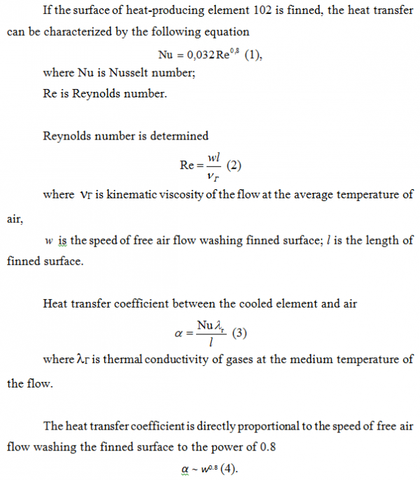
For the vortex chamber 101 of specific dimensions: height of the vortex chamber 101 - 25 mm, diameter 95 mm, diameter of the heat-producing element 102 - 15 mm, its shift from the axis of the vortex chamber 101 - 6 mm, width of the input channel of the vortex chamber 101 - 10 mm, air consumption 3 m3/hour, maximum tangential speed of air flow - about 11 m/s, which is more than 2 times the value of air flow speed at the air input vent to the vortex chamber 101 and in accordance with (4) leads to 50% increase of the heat transfer coefficient in comparison with existing designs of cooling devices.
Claim
1. A cooling device for electrical equipment, including
at least one fan with a directional air output vent from the body,
at least one vortex chamber with at least one air input vent to ensure air twist in the chamber connected to the air output vent from the fan body, and with a vent for the air output on at least one end,
at least one heat-conducting element located in the inner volume of the vortex chamber and implemented with the option to interact with at least one electrical equipment element located outside the vortex chamber, for its cooling.
2. The device of clause 1 wherein the heat-conducting element is in the form of heat pipe.
3. The device of clause 1 wherein the heat-conducting element is in the form of a rod from heat-conducting material.
4. The device of clauses 1, 2 or 3 wherein the outer surface of the heat-conducting element is made with a relief to dissipate the heat.
5. The device of clauses 1, 2 or 3 wherein the outer surface of the heat-conducting element is made with finning.
6. The device of clauses 1, 2 or 3 wherein the heat-conducting element is placed in the vortex chamber longitudinally, at a distance from the axis of the vortex chamber that is larger than the radius of air output vent at the end of the vortex chamber.
7. The device of clauses 1, 2 or 3 wherein it includes four heat-conducting elements placed in the vortex chamber longitudinally, at a distance from the axis of the vortex chamber, with a larger radius of air output vent at the end of the vortex chamber.
8. The device of clause 1 wherein the heat-conducting element is made in the form of a tube to ensure liquid cooling.
9. The device of clause 1 wherein the vortex chamber is made with tangential air input vent.
10. The device of clause 1 wherein the vortex chamber is made with spiral input vent.
11. The device of clause 1 wherein the vortex chamber is made from heat-conducting material.
12. The device of clause 1 wherein the vortex chamber is made with a set of heat-conducting elements thermally connected to the body of the vortex chamber or made as a one piece with it while the body of the vortex chamber is made with a base to ensure the contact with electrical equipment component for its cooling.
13. The device of clauses 11 or 12 wherein the body of the vortex chamber is made with the elements of the relief on the outside to increase the area of heat transfer.
14. The device of clause 1 wherein it includes heat-conductive base implemented with an option to tie in with an electric equipment element for its cooling while the heat-conducting element is connected on the outside vortex chamber with the heat-conductive base.
15. The device of clause14 wherein the heat-conductive base is located opposite the air output vent of the vortex chamber.
16. The device of clause15 wherein the heat-conductive base is implemented as a heat-dissipating radiator with its heat-dissipating area located opposite the air output vent of the vortex chamber.
17. The device of clauses 14 or 16 wherein the vortex chamber is made with a nozzle fixed from outside and connected with its inner volume through the air output vent at the end of the vortex chamber,
the heat-conductive base is implemented as a heat-dissipating radiator
while the end of the nozzle is directed at the heat-conductive base.
18. The device of clause 1 wherein the inner volume of the vortex chamber can be made in its cross-section in a cylindrical, elliptical or multi-faceted form.
19. The device of clause 1 wherein
it includes two fans
and the body of the vortex chamber is made with two air input vents arranged symmetrically to the axis to ensure air twist in the vortex chamber
while each air input vent is tied in with the air output vent from the body of a separate fan.
20. The device of clause 1 wherein it includes two reflection-symmetric vortex chambers mounted with their bodies tied in with each other and with the unidirectional arrangement of air input vents to ensure air twist in the chamber and connected to the air output vent from the body of one fan.
21. The device of clause 1 wherein it includes two pairs of reflection-symmetric vortex chambers made from heat-conducting material mounted in each pair with their bodies tied in with each other in the area of air input vents to ensure air twist in the chamber and with the unidirectional arrangement, that have their air input vents connected to the air output vent from the body of one centrifugal fan.
Abstract
The objective of the present invention is to intensify the convective component of heat transfer, which leads to increasing the energy efficiency of heat transfer device, reducing its weight and cost. The device includes a fan with directional air output vent from the body, vortex chamber (1) with air input vent (2, 3) to ensure air twist in the chamber (1) connected to the air output vent from the fan body and with a vent for the air output (10, 11) on one end, heat- conducting element (12) located in the inner volume of the vortex chamber (1) and implemented with the option to interact with electrical equipment element, located outside the vortex chamber (1), for its cooling.
(FR)La présente invention concerne l'intensification de la composante de convection de transfert thermique, ce qui entraîne une augmentation du rendement énergétique d'un dispositif de transfert thermique, réduisant son poids et son coût. La direction comprend un ventilateur qui comporte un évent de sortie d'air directionnel à partir du corps, une chambre à tourbillon (1) qui comporte un évent d'entrée d'air (2, 3) pour garantir le tourbillonnement d'air dans la chambre (1) raccordé à l'évent de sortie d'air du corps de ventilateur et qui comporte un évent pour l'entrée d'air (10, 11) sur une extrémité, un élément thermo-conducteur (12) positionné dans le volume intérieur de la chambre à tourbillonnement (1) et réalisé avec l'option d'une interaction avec un élément d'équipement électrique positionné à l'extérieur de la chambre à tourbillonnement (1), pour son refroidissement.
[img style=width%3A600px%3B]https://gord.ru/e107_media/28008de894/images/2017-12/wo2012008868_fig_01.png[/img]
[img style=width%3A600px%3B]https://gord.ru/e107_media/28008de894/images/2017-12/wo2012008868_fig_02.png[/img]
[img style=width%3A600px%3B]https://gord.ru/e107_media/28008de894/images/2017-12/wo2012008868_fig_03_04.png[/img]
[img style=width%3A600px%3B]https://gord.ru/e107_media/28008de894/images/2017-12/wo2012008868_fig_05_06.png[/img]
[img style=width%3A600px%3B]https://gord.ru/e107_media/28008de894/images/2017-12/wo2012008868_fig_07_08.png[/img]
[img style=width%3A600px%3B]https://gord.ru/e107_media/28008de894/images/2017-12/wo2012008868_fig_09_11.png[/img]
[img style=width%3A600px%3B]https://gord.ru/e107_media/28008de894/images/2017-12/wo2012008868_fig_12_13.png[/img]
[img style=width%3A600px%3B]https://gord.ru/e107_media/28008de894/images/2017-12/wo2012008868_fig_14_16.png[/img]
[img style=width%3A600px%3B]https://gord.ru/e107_media/28008de894/images/2017-12/wo2012008868_fig_17_18.png[/img]
[img style=width%3A600px%3B]https://gord.ru/e107_media/28008de894/images/2017-12/wo2012008868_fig_19_20.png[/img]
[img style=width%3A600px%3B]https://gord.ru/e107_media/28008de894/images/2017-12/wo2012008868_fig_21_22.png[/img]
[img style=width%3A600px%3B]https://gord.ru/e107_media/28008de894/images/2017-12/wo2012008868_fig_23_24.png[/img]
[img style=width%3A600px%3B]https://gord.ru/e107_media/28008de894/images/2017-12/wo2012008868_fig_25_26.png[/img]
 30+
30+