Номер международной заявки: PCT/RU2008/000803
Заявитель - автор: УВАРОВ Василий Андреевич
Международная патентная классификация (МПК): B64C 33/036 (2006.01)
Дата международной публикации: 17.12.2009
Приоритет от 11.06.2008 по заявке EA 200801643PARAMOTOR
Field of applicationThe invention relates to aviation, sports aviation and specifically to paramotor, used for powered paraplanes as their power unit. Powered paraplane as the present invention is an ultralight manned aircraft designed as a paraglider, i.e. parachute-type wing with strap-attached pilot’s harness. Powered paraplane being a safe and easy-controlled low-altitude aircraft can be used in sports events as a means of entertainment, in eco-tourism as a means of high-altitude terrain studies, e.g. by gamekeepers, inspectors of natural reserves, for flora and fauna researchers and in other cases where aircraft of this type may prove useful.
Background of invention
There is known paramotor of classical design incorporating a frame with elements for straps attachment. Pilot’s harness is on one side of the frame, on the other side of the frame there is an engine with a propeller installed on its shaft. Frame-fixed propeller guard is located around the propeller (BE №1011923 A6, IPC B64C, 2000, Fig.6 and Fig.7).
Design of the known paramotor is rather bulky hence it is hard to carry or transport by car.
There is known a more compact paramotor design which utilizes electric motor as a power-unit, charged from self-contained power supply (FR № 2817827 A1, IPC 7 B64C 31/036, 2002).
The known aircraft contains load-bearing frame. On one side of the frame there is fitted pilot’s harness, made of textile with hard seat, on the other side there is fixed electric motor and self-contained power supply.
The propeller in the known design contains three blades folding out inertially by rotation. The propeller is detachable and is cantilever fitted on electric motor shaft for pilot’s safety and straps protection since propeller guard is absent.
Notwithstanding compactness of the known design it takes too much space in a car and it needs special container to be transported. It weighs too much that makes it rather inconvenient to carry regardless of propeller guard absence.
Moreover modern self-contained power supplies service life is rather short that reduces flight duration.
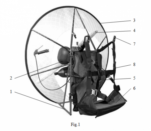
In the photograph (Fig.1) there is depicted detachable paramotor (“Miniplane M”;
ссылка known to priority date of the present invention. This is the lightest and most compact paramotor out of the range of paramotors presented on the market now.
The known paramotor incorporates load-bearing frame 1. On one side of the frame 1 there is fixed a two-cycle motor 2 on fuel oil, a fuel tank (cannot be seen in Fig. 1) and a detachable guard 3 of a propeller 4.On the other side of the frame 1 there is fixed pilot’s harness 5 made of textile with hard seat 6. Powered paraplane straps (not depicted in Fig. 1) are attached to buckles 7 on straps 8 which pilot fastens to the frame 1 with fixation on pilot’s harness 5.
In the known paramotor the frame 1 cannot be disassembled. In the process of disassembling we dismount the guard 3, propeller 4, motor 2, fuel tank and pilot’s harness as well. All the details numbered are packed into a plastic container which takes full space of a midget car luggage compartment. It proves that design is not compact enough, it is difficult to transport by car and impossible to carry over for a long time. Plastic container size goes out of airline-approved limits.
Substance of inventionEngineering task, the present invention focuses on, is to elaborate paramotor detachable design able to form compact luggage in a disassembled condition, easy transportable either by car or by air or easy portable for man which will provide for paramotor transportation without any transport means. Pilot will be able to get to off-road takeoffs all by itself and get out of such places unassisted in cases of emergency landing.
The engineering problem specified is solvable by paramotor containing a frame, a power unit and power unit controls, a detachable propeller adjusted on take-off shaft of the power unit, frame-fixed pilot’s harness with mating back and seat, draft belts for pilot safety and for jointing to free ends of a powered paraplane and distance bars moving apart the draft belts for jointing to free ends of the powered paraplane, above the harness seat lengthways.
The frame consists of motor and bearing parts. On one side of the motor part there is power unit fixed and on the other side there is pilot’s harness. The motor and bearing parts of the frame have solid lateral sides and are jointed hinged or detachably. The lateral sides of the motor and bearing parts should be spaced partially at least alongside geometry edges obtained by planes conjugating of four lateral faces of a figure. In volume of this figure there is power unit.
If we meet requirements mentioned above it makes it possible to elaborate an assembly which forms compact and portable luggage which cage consists of frame elements only.
As a rule the frame is made of iron bars.
Design is specified by particular cases of its constructing.
In the first version the frame motor part has a rectangular shape with protruding bars situated perpendicular to its plane at two angles on one side and with hinges for jointing to the frame bearing part at its two angles on the other side.
The frame bearing part in this version has a rectangular shape as well with protruding bars spaced perpendicular to its plane at two angles on one side. The ends of the protruding bars of the bearing part are jointed to the motor part hinges.
Furthermore in this case the frame involves a fixture element in the form of two parallel bars. Their ends are jointed firmly by a perpendicular bar on one side. Free ends of the parallel bars of are attached hinged to the motor part lateral sides. By the ends coupled by the perpendicular bar the fixture element is fitted detachably on the frame bearing part providing perpendicular structure of planes of the motor and bearing parts.
Besides in this frame structure each distance bar is formed by short and long bars firmly linked at right angle. Free ends of the long bars are fitted detachably on the motor part hinges alongside their opposite lateral sides with the possibility to spin around the motor part lateral sides and around the axle perpendicular to these sides.
In the second version the motor part has a rectangular shape with protruding joint bars spaced perpendicular to the motor part plane at its two angles on one side. The bearing part has a rectangular form as well with protruding joint bars situated perpendicular to the bearing part plane at its two angles on one side, and with protruding bearing bars spaced perpendicular to the motor part plane at its two angles on the other side. Their ends are coupled by a crossbar.
Free ends of the motor and bearing part joint bars are hinge coupled in the second version.
In the third version the motor and bearing parts have rectangular shapes. They are jointed detachably and spaced in one plane.
The bearing part is fabricated with protruding bearing bars situated perpendicular to its plane at two angles on the side opposite to the side conjugated to the motor part. Ends of the bearing bars are linked by a crossbar.
In the third version each distance bar is formed by short and long bars firmly linked at right angle, herein free ends of the long bars of the distance bars are fixed at two angles of the motor part from the side opposite to the one conjugated to the bearing part with possibility to spin around the axles parallel to the motor part lateral sides.
We have mentioned versions of paramotor frame design implementation which renders it possible to develop robust and strong construction of luggage cage while transforming the frame into transportable form that will be shown in greater detail in the following examples. Thereby there will be developed design similar to the one adjacent to human back. This construction is kin to section of a knapsack or a backpack construction with a square-set frame that facilitates transportation considerably.
One of important developments of the design concerns pilot’s harness. Back and seat of the harness have the possibility of relative swivel. The harness back is supplied with turnoff side -sections, the harness seat is made in the form of fold-out sections. In this case pilot’s harness can serve as a sheath of the assembly transformed into transportable form which prevents from using add-on container for transportation of an assembled paramotor.
In all versions there can be envisaged detachable propeller guard in the form of radial struts and arcs. The radial struts ends are attached to the motor part, the arcs are linked to the other two ends of the radial struts in order to form a protecting circle around the propeller. It is possible when detachable propeller guard arcs related to the frame contiguously, are attached to its bearing part.
The motor and bearing parts can be manufactured of iron bars in the form of hollow shape lengths or tubes made of steel, titanium or aluminium alloy. Similar lengths can be used for the radial struts of the detachable propeller guard. Detachable propeller guard arcs can be made of hollow shape lengths or tubes made of elastic material.
The assembly can be equipped with straps bonded with the motor part and located on the side of pilot’s harness back. While traveling they can be used as shoulder-straps of a knapsack. While in flight the straps are used for extra safety of a pilot.
Realization of inventionRealization of invention is shown by the example of specific paramotor constructing which is illustrated in diagrams. In diagrams (Fig. 2-11) there is represented design of an assembly with a frame made according to the first version.
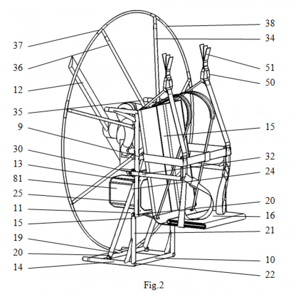
In Fig. 2 there is demonstrated solid view of an assembled paramotor in accordance with the first version of frame design from pilot’s harness side (powered paraplane is not shown as in all other illustrations since powered paraplane design as a whole has nothing to do with the invention).
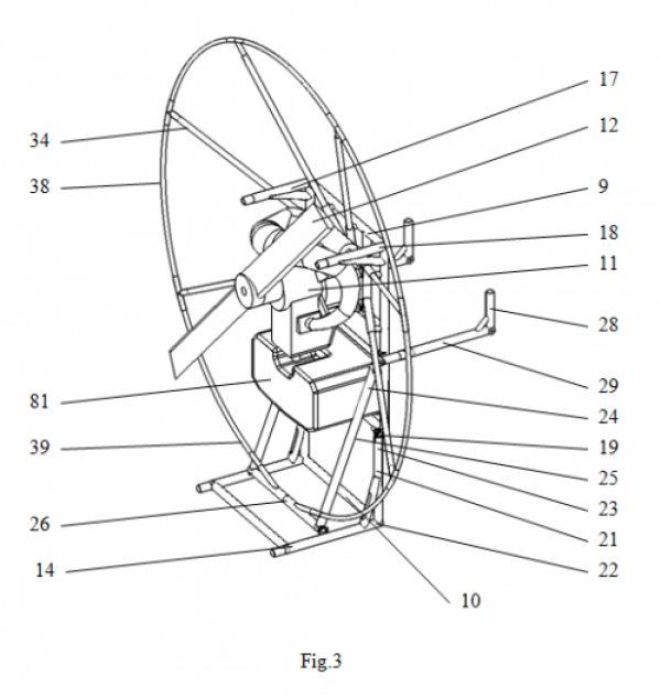
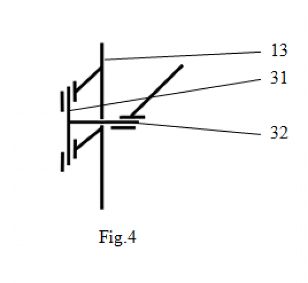
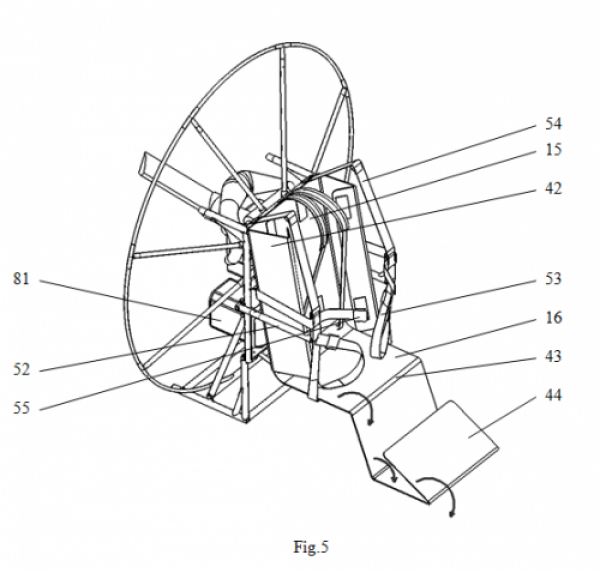
In Fig. 3 there is shown solid view of this paramotor from the side of an engine without pilot’s harness. In Fig.4 there is represented kinematic sequence of mount pivots of distance bars fixed to the motor part of the frame. In Fig. 5 there is demonstrated solid view of the paramotor from the side of pilot’s harness with fold-out back and seat sections.
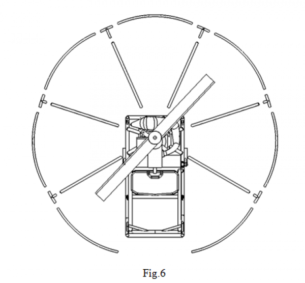
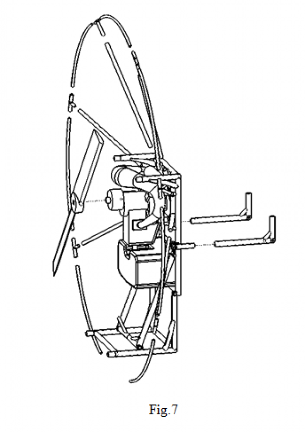
Assembling and disassembling of the paramotor are shown in Fig.6, where we can see the paramotor, front elevation from the side of propeller and in Fig.7 where the paramotor solid view is represented. In these figures pilot’s harness is not shown, there is illustrated detachment of dismountable details.
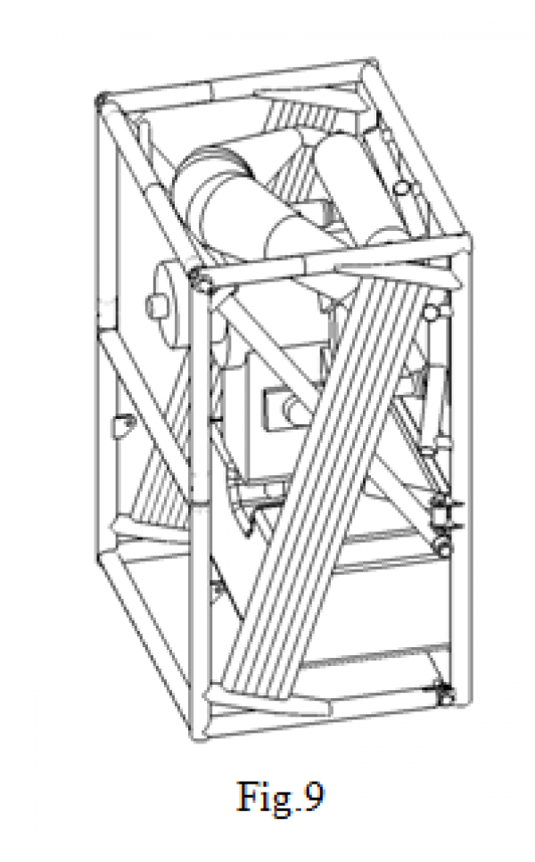
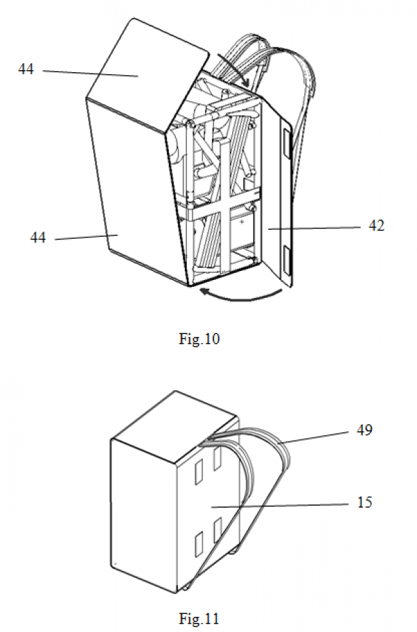
The paramotor design in an assembled form is illustrated in a diagram in Fig.9. In Fig.10 there is shown how pilot’s harness transforms into design sheath, solid view. In Fig.11 there is illustrated a fully closed container for transportation, solid view.
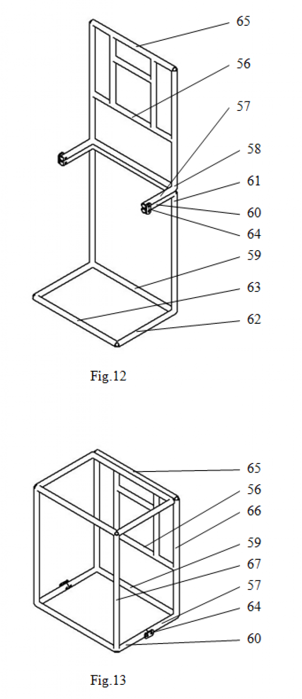
In Fig.12, 13 there is represented frame design, made in compliance with the second version, in Fig 12 - in flight, in Fig.13 – in an assembled transportable form.
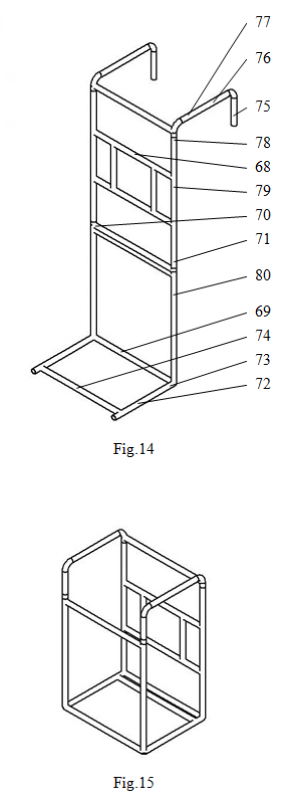
In Fig. 14, 15 there is demonstrated frame design made in accordance with the third version, in Fig. 14 - in flight, in Fig. 15 – in an assembled transportable form.
Paramotor contains a frame consisting of two conjugating parts, motor 9 and bearing part 10. The motor part 9 is equipped with a power unit 11 with a detachable propeller 12 on its takeoff shaft. Power unit controls are not illustrated in diagrams.
The motor 9 and bearing 10 parts are made with solid lateral sides 13, 14 formed by iron bars.
On the side opposite to the power unit 11 install location of the motor part 9 there is fixed pilot’s harness which has mating back 15 and seat 16.
The motor part 9 has a rectangular shape with protruding bars 17 (Fig.3), situated perpendicular to the motor part plane 9 at its two angles 18 on one side, and hinges 19 for linking to the bearing part 10 at its two angles 20 (Fig. 2) on the other side.
The bearing part has a rectangular shape as well with protruding bars 21 spaced perpendicular to the bearing part plane 10 at its two angles 22 on one side. The ends 23 of the bars are linked to the hinges 19 of the motor part 9.
On the motor part 9 along its lateral sides 13 on their middle part there are hinge fixed ends 24 of a fixture element which has two parallel bars 25, firmly linked by a perpendicular bar 26 on the other side. The ends 27 of the parallel bars 25 of the fixture element are fitted detachably on the bearing part 10.
To the lateral sides 13 of the motor part 9 there are jointed distance bars with short 28 and long 29 bars, firmly hinge linked 30 at right angle (Fig.2).
Kinematic scheme of hinges 30 is represented in Fig. 4. The hinges 30 make it possible for the distance bars (28, 29) to spin around the axle 31 that provides for its rotation around the motor part 9 sides 13 and around the axle 32 perpendicular to the sides 13.
The distance bars (28,29) are linked to the hinges with the help of detachable joints 33 (Fig.2) The distance bars (28,29) are fabricated in the way to make it possible for the short bar 28 to be bound to projection of the protruding bar 17 of the motor part 9. And the end of the long bar 29 should be linked to the bearing part, to projection of its lateral side 14.
The bars length 28, 29 of each distance bar (28, 29) is chosen in accordance to the following requirement. If the distance bars (28,29) are linked to the protruding bar 17 of the motor part 9 and to the lateral side 14 of the bearing part 10, the frame 9, 10 ,in its traveling condition, forms rectangles by each of its lateral sides 13,14 of its both parts 9,10 and corresponding distance bars (28,29). These rectangles form perimeters of two lateral sides of luggage in which the paramotor transforms in its transit condition. Thus, there is built up a design where the lateral sides 13 and 14 of the motor 9 and bearing parts 10 are spaced partially at least alongside geometry edges obtained by planes conjugating of four lateral faces of a figure. In volume of this figure we have the power unit 12.
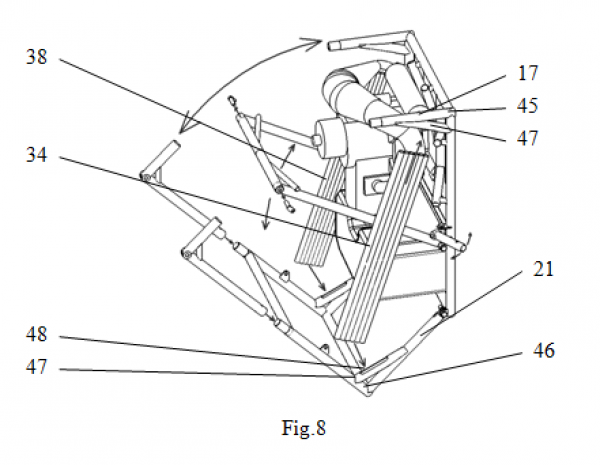
Radial struts 34 ends 35 of the propeller guard 12 (Fig.2) are fixed to the motor part 9, arcs 38 are fixed by fixture elements 37 at their ends 36. The arcs 38 contiguous to the bearing part 10 are attached by their ends 39 to the bar 26 of the fixture element (25, 26).
Pilot’s harness back 15 and seat 16 are linked to each other in the way to make relative swivel possible at one level with the hinges 19 binding the motor 9 and bearing parts 10.
The back 15 length is equal to the motor part 9 length and pilot’s harness back is made with folding lateral rectangular sections 42, their width is equal to the protruding bars length 21.
Pilot’s harness seat 16 length is equal to the length of the protruding bars 21 of the bearing part 10. The seat 16 consists of three series-fold-out rectangular sections 44, bound with the seat alongside external edge 43 (Fig.5). Overall length of the first two sections is equal to the length of the motor part 9 and pilot’s harness back 15, length of the third, the outermost is equal to the length of the protruding bars 21 of the bearing part and to the length of the seat 16, mentioned above.
By detaching of the radial struts 34, arcs 38, detachable propeller 12 and distance bars (28,29) we unload the bar 26 of the fixture element (25,26) which moves in the direction of the protruding bars 17 of the motor part 9, the bearing part moves hinged 19 subsequently.
Each distance bar (28, 29) is linked by the end of the short bar 28 to the protruding bar 17 of the motor part 9, and by the end of the long bar 29 to the bearing part 10, to projection of its side 14. The assembled construction is strengthened by the fixture element attached inside (25, 26). The hinges 30 are swiveled inside.
Mounting attachments of the motor part 9 with the protruding bars 17 and mount attachments 46 of the bearing part 10 with the protruding bars 21 have details 47 strengthening the attachment, situated inside the angles formed by the attached details. Details are slotted 48 (fig.3). Slots are inverted outbound angle vertices mentioned. The detached radial struts 34 and arcs 38 are fagot fitted into the slots 48 (Fig. 8).
Pilot’s harness back 15 remains at the point of the motor part 9 where it is attached in flight. Folding lateral rectangular sections 42 cover the construction on each side. Pilot’s harness seat is underneath. Two first folding out rectangular sections 44 bound to the seat 16 are situated alongside the rear part of the construction. The outer section 44 covers the construction at the top (Fig.10). The details of pilot’s harness 15, 16, 42, 44 can be fastened by a zip in an assembled condition.
The paramotor transformed into fully closed container illustrated in Fig. 11, is provided with straps 49 for carrying the assembly situated on the side of pilot’s harness back 15. In flight the straps are used for extra safety of a pilot.
Harness system of load-bearing belts, demonstrated in Fig.2 contains buckles 50 for powered paraplane straps 51 fixing, supporting belts 52, lap belts 53 and chest belts 54 with buckles 55 (Fig. 5). The chest 54 and supporting belts 52 are moved apart by the distance bars (28, 29) in the line of pilot’s seat 16.
In transit condition the paramotor harness system elements are kept inside. There are only straps 49 left if the assembly is going to be carried. In case of transportation by any means of transport they can be kept inside as well.
The invention envisages various versions of frame constructing.
In Fig. 12 and 13 there is demonstrated version involving a frame with motor part 56 of a rectangular shape with protruding joint bars 57, spaced perpendicular to the motor part 56 plane at its two angles 58 on one side.
Bearing part 59 has a rectangular form as well with protruding joint bars 60 located perpendicular to the bearing part plane 59 at its two angles 61 on one side and with protruding bearing bars 62 spaced perpendicular to the motor part 56 plane at its two angles 62 on the other side. The ends of the protruding bearing bars are linked by a cross bar 63.
Free ends of the joint bars 57 and 60 are coupled by hinges 64.
The frame assembles by swiveling of the bearing part 59 relative to the motor part 56 on hinges 64 till contact with upper part 65 of the motor part 56 which forms a cage as a result like in the first version where lateral sides 66 and 67, correspondingly, of the motor 56 and bearing 59 parts are spaced alongside geometry edges, obtained by conjugating of planes of four lateral figure faces. In volume of this figure there is power unit 12 (in Fig. 12 and 13 it is not shown).
In Fig.14 and 15 there is demonstrated the third possible version of paramotor frame constructing in compliance with the invention. In this version motor part 68 and bearing part 69 have rectangular forms and are linked detachably situated in one plane in zones 70 and 71.
The bearing part is supplied with protruding bearing bars 72, situated perpendicular to its plane at its two angles 73 from the side opposite to the one conjugated to the motor part 68. The bearing bars 72 ends are linked by a crossbar 74.
Distance bars in this version come with short 75 and long 76 bars firmly bound at right angle. The distance bars (75, 76) are fixed by free ends 77 of the long bars 76 at the motor part 68 angles 78 with the possibility to spin around axles, parallel to lateral sides 79 of the motor part 68.
In this version bringing the frame into the assembled form is performed by detachment of the bearing part 69 and its further attachment by its ends 72 to the point of original conjugation with the motor part 68, but this time the attachment will be perpendicular. Then the distance bars (75, 76) reverse end for end and link by free ends of the short bars 75 to projection of lateral sides 80 of the bearing part 69 thus shaping a closed cage with the power unit inside (in Fig.14 and 15 not shown).
In either version of frame constructing as a power unit 12 there can be used two-cycle engine on fuel oil with built-in reduction unit or electric motor. Fuel tank 81 referred to in the first case and power supply source in the second case are attached to the motor part 9, 56, 68, however they can be attached to the bearing part 10, 59, 69, too.
For frame fabricating in all its variations there are used iron bars in the form of hollow-shape lengths or tubes made of steel, titanium or aluminium alloy which are welded. Similar lengths can be utilized for the radial struts 34. The arcs 38 are manufactured of hollow-shape lengths or tubes of elastic material, e.g. of polyamide.
Detachable joints manufacture can vary. If details are made of hollow tube lengths there can be joints entering one into another and fixed by bar details, which may be forced attached or self attaching. For the radial struts 34 attachment there can be used tightening cables (which are not shown in diagrams) with locks providing cable tension or fixation.
Pilot’s harness is made of fabric of flexible material. Fabric may be woven out of synthetic fibers or sheet polymer material.
Thereby realization of invention affords to get a light and small-sized construction in an assembled condition. There is no need in special container for the paramotor transportation. All elements required for the paramotor land transportation are present in its flight configuration. The paramotor in its assembled and packed condition forms compact luggage, a knapsack which can be easily transported by air and carried pickaback in long-distance trips.
Claim
1. Paramotor incorporating a frame, power unit, power unit controls, detachable propeller installed on power unit take-off shaft, pilot’s harness attached to the frame with mating back and seat, draft belts for jointing to free ends of powered paraplane and for pilot’s safety, and distance bars for moving apart of the draft belts for jointing to the free ends of the powered paraplane above the pilot’s harness seat in the line of its length. The frame consists of motor and bearing parts. On one side of the motor part there is the power unit fixed, the other side there is pilot’s harness attached. The motor and bearing parts are made with solid lateral sides and are jointed hinged or detachably. The lateral sides of the motor and bearing parts should be spaced partially at least alongside geometry edges obtained by planes conjugating of four lateral faces of a figure. In volume of this figure there is power unit.
2. Paramotor according to point 1 is notable for its frame manufactured of iron bars.
3. Paramotor according to point 2 is notable for incorporating motor part which has a rectangular shape with protruding bars spaced perpendicular to its plane at two angles on one side and with hinges to joint to bearing part of the frame at its two angle on the other side. The bearing part has a rectangular shape as well with protruding bars located perpendicular to its plane at two angles on one side. The protruding bars ends are linked to the hinges of the motor part. Furthermore the paramotor contains fixture element in the form of two parallel bars firmly linked by their ends by a perpendicular bar on one side. Free ends of the parallel bars are hinge jointed to the motor part lateral sides. The ends coupled by the perpendicular bar are detachably jointed to the bearing part of the frame providing for perpendicular structure of the motor and bearing part planes.
4. Paramotor according to point 3 is characterized by containing distance bars which are formed by short and long bar linked firmly at right angle herein the ends of the long bars of the distance bars are fixed to the motor part hinges detachably alongside its opposite lateral sides with the possibility to spin around the motor part lateral sides and around the axle perpendicular to these sides.
5. Paramotor according to point 2 is notable for its motor and bearing part which have rectangular shapes. The motor part has a rectangular shape with protruding joint bars situated perpendicular to the motor part plane at its two angles on one side. The bearing part has a rectangular form as well with protruding joint bars located perpendicular to the bearing part plane at its two angles on one side and with protruding bearing bars situated perpendicular to the motor part plane at its two angles on the other side. Their ends are linked by a crossbar herein the joint bars free ends of the motor and bearing parts are hinge coupled.
6. Paramotor according to point 2 is notable for the motor and bearing parts having rectangular forms and being linked detachably and situated in one plane. The bearing part is made with protruding bearing bars spaced perpendicular to its plane at two angles on the side opposite to the side contiguous to the motor part, whereas the bearing bars ends are linked by a crossbar. Each distance bar is made of short and long bars firmly linked at right angle. Free ends of the long bars are fixed at two angles of the motor part from the side opposite to the side contiguous to the bearing part with the possibility to spin around the axles parallel to the motor part lateral sides.
7. Paramotor characterized by the possibility of relative swivel of pilot’s harness back and seat. The back is constructed with turnoff lateral sections, the seat is made with folding-out sections.
8. Paramotor according to point 1 notable for being supplied with a propeller guard of a detachable propeller, constructed of radial struts attached to the motor part by its ends, and arcs, bound to the other ends of the radial struts in order to form a protecting circle around the propeller.
9. Paramotor according to point 8 notable for having propeller guard arcs attached to the bearing part of the frame contiguously.
10. Paramotor according to point 2 notable for utilizing hollow-shape lengths or tubes of steel, titanium or aluminium alloy as iron bars for fabricating of the motor and bearing parts.
11. Paramotor according to point 8 characterized by using hollow-shape iron lengths or tubes made of steel, titanium or aluminium alloy as the radial struts of the propeller guard; and by using hollow-shape lengths or tubes made of elastic material as propeller guard arcs.
12. Paramotor according to point 1 notable for being supplied with straps bound to the frame motor part and situated from the side of pilot’s harness back.
Abstract
Engineering task, the present invention focuses on, is to elaborate paramotor detachable design able to form compact luggage in disassembled condition, easy transportable either by car or by air or easy portable for man which will provide for paramotor transportation without any transport means. Pilot will be able to get to off-road takeoffs all by itself and get out of such places unassisted in cases of emergency landing. Paramotor incorporates a frame, power unit, power unit controls, detachable propeller installed on power unit take-off shaft, pilot’s harness attached to the frame with mating back and seat, draft belts for jointing to free ends of powered paraplane and for pilot’s safety, and distance bars for moving apart of the draft belts for jointing to the free ends of the powered paraplane above the pilot’s harness seat in the line of its length. The frame consists of motor and bearing parts. On one side of the motor part there is the power unit fixed, on the other side there is pilot’s harness attached. The motor and beating parts are made with solid lateral sides and are linked hinged or detachably. The lateral sides of the motor and bearing parts should be spaced partially at least alongside geometry edges obtained by planes conjugating of four lateral faces of a figure. In volume of this figure there is power unit.
 30+
30+