Номер международной заявки: PCT/RU2011/000812
Заявитель - автор: СОКОЛОВ Александр Николаевич
Международная патентная классификация (МПК): H05K 7/20 (2006.01), F25B 9/04 (2006.01), G12B 15/02 (2006.01)
Дата международной публикации: 13.12.2012
Приоритет от 09.06.2011 по заявке EA 201100856
Liquid cooling unit for electrical equipment (variants)
Pertinent ArtThe invention relates to instrument construction and to electrical engineering, and specifically to the liquid cooling for electrical equipment, which can be used to cool the units of various electronic devices, in particular for cooling computers, game consoles and laptops CPUs, video card processors and their components, power supply units, electrical equipment as well as other electrical devices, such as film projectors, voltage regulators, transformers, converters, rectifiers, etc.
State of the ArtMost electronic devices release heat while operating. Thus, a CPU and video processor of a modern video card installed on a computer can generate more than 200 watts of heat each. In order to dissipate such quantity of heat and maintain manufacturer-recommended temperature regimes for the safe operation of electronic devices, active cooling systems are required.
In most cases, active air cooling systems are used, but because of their design features, namely the rigidity of the entire device, the heat in such systems is dissipated directly into the small volume of the computer case, and in order to increase the cooling device capacity, larger cases must be used, which is not always possible, particularly in terms of server solutions.
Another popular option for a cooling system is liquid cooling, a closed circulation system of liquid coolant, most often water or an aqueous solution with additives.
Typically, such cooling systems consist of a cooling block, which is a hollow construction made of heat-conducting material, through which the liquid coolant is being pumped and the outer side of which is thermally connected with a heat source in order to cool it, a pump which maintains circulation of the coolant in the system, a radiator with a fan in order to cool the liquid coolant itself, a reservoir in order to replenish and maintain the level of the liquid coolant in the system and a system of flexible hoses connecting all the elements together.
In terms of efficiency, in comparison with air cooling systems, liquid cooling systems can dissipate much more heat: also the flexible hoses used in them make it possible to divide the system and position its components on a considerable distance from each other, for example, the radiator may be placed outside the case or, on the contrary, close to each other to make the system compact.
There is a CPU cooling device where the liquid cooling block with units of liquid coolant supply and discharge in the form of nozzles is thermally connected to the processor. This construction does not use a reservoir for liquid coolant. The pump is directly attached to the radiator, connected to a liquid cooling block by means of flexible hoses (US 2006/0021737 A1, IPC H05K 7/20, 2006).
There is a CPU liquid cooling device where a pump, which maintains circulation of the liquid coolant, reservoir for storing and replenishing the liquid coolant in the system and liquid cooling block thermally connected to a heat source in order to cool it, are made in one case, located directly in the computer's case. (US 2010/0326636 A1, IPC F28D 15/00, 2010).
In this well known device, in the same way as in that described above, the liquid cooling unit is not equipped with a special construction aimed to intensify dissipation of heat by the liquid coolant from its case coupled with the heat producing CPU of the computer.
Typically, the design of the liquid cooling unit coupled with a heat-producing component of the electrical equipment, represents a case made of heat conducting material with channels along the heat-sensing surface through which the cooling liquid flows (US 6313990 B1, IPC H05K 7/20, 2001).
These channels can be made through a wide variety of ways. In particular, one design of a liquid cooling block is a case made of heat conducting material having a surface with lots of equally spaced ridges, covered with a cover. The liquid coolant is supplied between the ridges in different areas as well with different flow rates, which allows to provide zonal change in the amount of liquid coolant supplied for cooling, depending on the temperature map of the cooling processor (US 2010/0241278 A1, IPC G05D 23/19, 2010).
Thus, at the current stage of development of technology, which, in particular, is illustrated by the above-described constructions, heat from electrical equipment is removed using liquid cooling blocks, where heat is transferred to the liquid coolant, and their efficiency is largely determined by the flow rate of the liquid coolant. At the same time, the thermotechnical and hydrodynamic perfection of liquid cooling block directly affects the efficiency of the entire cooling system. Intensifying the heat exchange process, reducing thermal and hydrodynamic resistance of a liquid cooling block shall allow to lower overall energy consumption for pumping liquid through the system, as well as feed a greater number of liquid cooling blocks from one pump, and, most importantly, reduce the temperature of the electric equipment being cooled, which positively affects its life time.
Substance of InventionThe objective of this invention is to intensify the heat exchange process and to improve the hydrodynamic performance of the liquid cooling block that is used in electrical equipment liquid cooling systems, which ultimately leads to increased energy efficiency of the entire cooling device.
According to the first version of the invention, the solution to this problem is provided through a liquid cooling block for electrical equipment containing:
- a case made of heat-conducting material with possibility of thermal coupling with at least one component of electrical equipment for its cooling and having at least one vortex chamber in the form of a cavity with at least one liquid coolant input channel, configured with possibility of supplying the liquid coolant with its swirling in the vortex chamber and liquid coolant output channel from the vortex chamber;
- a liquid coolant supply node communicating with the liquid coolant input channel of the vortex chamber,
- a liquid coolant discharge node communicating with the liquid coolant output channel of the vortex chamber.
The case of liquid cooling block can be made with several vortex chambers. At that, the vortex chambers may be arranged in two parallel rows, in each of which the vortex chambers are also arranged in parallel.
Each input channel for the liquid coolant in the vortex chambers can communicate directly with a liquid coolant supply node. Each output channel of the liquid coolant in the vortex chambers can communicate directly with a liquid coolant discharge node.
There may be cases when the vortex chambers communicate with one another sequentially. Output channel of the liquid coolant of one vortex chamber communicates with input channel of the liquid coolant of another vortex chamber. At that, input channel of the liquid coolant of the first vortex chamber communicates with the liquid coolant supply node, and the output channel for the liquid coolant of the last vortex chamber communicates with the liquid discharge node.
The second version of the invention provides the cooling block for electrical equipment to include:
- a case made of first and second parts, the first of which is made of heat-conducting material with a possibility of thermal coupling with at least one component of electrical equipment for its cooling and having at least one vortex chamber in the form of a cavity with at least one liquid coolant input channel, configured with a possibility of supplying the liquid coolant with its swirling in the vortex chamber and liquid coolant output channel from the vortex chamber;
- a liquid coolant supply node communicating with the liquid coolant input channel of the vortex chamber,
- a liquid coolant discharge node communicating with the liquid coolant output channel of the vortex chamber.
At that, at least a part of a cavity in the vortex chamber is arranged in the fist part of the case.
In this version the case of liquid cooling block may also be made with several vortex chambers, each of which has at least a part of a cavity in the chamber arranged in the fist part of the case. At that, the vortex chambers may also be arranged in two parallel rows, in each of which the vortex chambers are also arranged parallel.
Each input channel of the liquid coolant in the vortex chambers in this version can communicate directly with a liquid coolant supply node. Each output channel of the liquid coolant in the vortex chambers can communicate directly with a liquid coolant discharge node.
There also may be cases when the vortex chambers communicate with one another sequentially. Output channel of the liquid coolant of one vortex chamber communicates with input channel of the liquid coolant of another vortex chamber. At that, the input channel of the liquid coolant of the first vortex chamber communicates with the liquid coolant supply node, and the output channel of the liquid coolant of the last vortex chamber communicates with the liquid coolant discharge node.
The first and second parts of the case may be coupled in the plane of the axes of the vortex chambers and the second part of the case is made with extra cover. At the same time in the second part of the case at the area of coupling with extra cover and / or on the surface of the extra cover facing the second part of the case the channels may be made which connect the output channel of the liquid coolant of one vortex chamber with the input channel of the liquid coolant of the another vortex chamber.
It is possible when the first part of the case is made in the form of the cover, and the second — in the form of the block with at least one input channel of the liquid coolant made in it, and output channel of the liquid coolant from the vortex chamber, as well as with a liquid coolant supply node and a liquid coolant discharge node installed thereon.
It is possible when the first part of the case is made in the form of the block with several vortex chambers, and the second — in the form of the cover with two cavities. One cavity is connected to the input channels of the liquid coolant of the vortex chambers and liquid coolant supplying node. The second cavity is connected to the output channels of the liquid coolant from the vortex chambers and liquid coolant discharge node. At that, there is an option when the first part of the case is made with the cavity communicating with output channels of the liquid coolant from the vortex chambers, which forms a common spatial figure with the second cavity of the second part of the case.
It is possible when the case is made with several vortex chambers with the first and second parts thereof being coupled in the plane of the axes of the vortex chambers and the second part of the case — configured with extra cover. In this case, the first and second parts of the case are made with a cavity communicating with the output channels of the liquid coolant from the vortex chambers and liquid coolant supply node assembled on the extra cover. At that, the second part of the case is made with a closed by extra cover cavity interconnected with the input channels of the liquid coolant of the vortex chambers and the liquid coolant supplying node configured on the extra cover.
In both versions of the invention, the following features of the invention are possible, which are valid for construction with one vortex chamber and for those with several vortex chambers.
The case of liquid cooling block can be provided with at least one additional means of heat transfer from the component of electrical equipment to the case, which, in particular, may be made in the form of a heat pipe of the known construction.
Output channel of the liquid coolant from vortex chamber may be located in one of the end faces of its cavity.
Input channel of the liquid coolant in the vortex chamber and output channel of the liquid coolant from the vortex chamber is preferably arranged relative to one another with the axes crossed at an angle of 90 degrees.
It is preferred that the axis of the input channel is shifted relative to its tangential position towards the axis of the vortex chamber in order to create impact jet. All the vortex chambers as only a part of them may be made that way, if there are several of them in the case.
Input and / or output channel of the vortex chamber can be made in cross-section or in the form of a circle, or in the form of an ellipse, or in the form of a polygon.
Liquid coolant supply node and / or liquid coolant discharge node typically contains fittings for connecting pipes. However, the other known designs, which allow the passage of the liquid coolant in the liquid cooling system, may be used.
The inner surface of cavity of the vortex chamber can be made relief in order to increase the heat exchange intensity. It is possible when the inner surface of cavity of the vortex chamber is made with fins. The fins may be arranged radially or in a spiral evolving as in the direction of motion of the liquid coolant in the vortex chamber as against it.
The cavity of the vortex chamber in the cross section in the preferred versions may have either circular, or elliptical, or polygonal form.
The outer surface of the case can be made with relief for its additional convection cooling. In particular, the outer surface of the case can be made with fins. Relief or fins on the case are usually made from the side of the cooling liquid supply node.
Description of Graphic Materials Illustrating the Invention Fig. 1 shows the principle of operation, and Fig. 2 represents a schematic construction of the liquid cooling block.
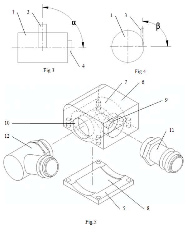
Fig. 3 and 4 show the relative angular axes position of the input and output channels of the vortex chamber.
Fig. 5 (isometric view) and Fig. 6 (side view) represents the simplest example of implementation of the invention, where the case is made of two parts with one vortex chamber in the form of an elliptical cylinder.
Fig. 7 represents the liquid cooling block with several vortex chambers and general cooling liquid supply and discharge systems. Fig. 8 represents the first part of the case of this block with vortex chambers, and fig. 9 represents the same unit in the assembled view (isometric view)
Fig. 10 shows an example of implementation of liquid cooling block the case parts of which are coupled on the plane of axes of several parallel vortex chambers.
Fig. 11 represents the case of liquid cooling unit with sequential connection of the parallel vortex chambers.
Fig. 12 represents the case of the liquid cooling unit with vortex chambers arranged in two parallel rows.
Fig. 13 represents the most common liquid cooling system, allowing the use of the liquid cooling unit made in accordance with this invention.
Fig. 14 represents a server cooling scheme that uses more than one circulation loop of the liquid coolant.
Fig. 15 represents a liquid cooling system with the sequential connection of several liquid cooling blocks.
Fig. 16 represents a simulated vortex chamber with the trajectory of an elementary particle of the cooling liquid.
Fig. 17 represents a way to create impact jets in the vortex chambers of liquid cooling block.
Detailed Description of Invention Implementation ExamplesDevice represents a vortex chamber 1 (Fig. 1, 2), which is being a cavity inside the case 2 made of heat-conducting material with a possibility of thermal coupling at least by one side with one component of electrical equipment (not shown on Fig. 1,2) for its cooling. The case 2 is designed with input channel 3 of the liquid coolant, which provides the possibility to supply liquid coolant with its swirling in the vortex chamber 1, and output channel 4 of the liquid coolant from the vortex chamber 1. Case 2 may be additionally provided with one or more additional heat transfer means (not shown) from electrical equipment components to the case 2. There may be used rods made of heat-conducting material, heat pipes, whose designs are well known in this field of technology. Using the additional means of heat transfer, the heat from the other components of electrical equipment that require cooling can be carried onto case 2.
Swirl (cyclone) chamber 1, as a heat exchanger, is characterized by a high rate of rotation of the liquid coolant, possibility of obtaining the liquid coolant velocity in the internal volume above the inlet velocity, possibility of creating a shock separated flow (turbulent flow) by means of finning or creating relief (not shown), of the inner surface of the vortex chamber 1.
High intensity of rotation of the liquid coolant in the vortex chamber 1 leads to a reduction of the required volume of pumped liquid coolant. Before leaving the vortex chamber 1, the same volume of the liquid coolant repeatedly washes the walls of the vortex chamber 1, which at the high speeds of the liquid coolant and through the creation of shock separated flow while flowing around the components of finning or relief of the inner surface of the vortex chamber 1, leads to a significant increase in the convective component of heat exchange, and consequently - to improving energy efficiency of the entire heat exchange device.
The internal volume of the vortex chamber in the cross section can have cylindrical or elliptical shape, or be multi-faceted. The inner surface of the chamber itself can be made both smooth and relief, or with finning, as noted above. The fins may be arranged radially or in a spiral evolving as in the direction of motion of the cooling liquid in the vortex chamber 1 as against it.
Tilt angles α and β (Fig. 3, 4) of the input 3 and output 4 channels may vary in the range to ensure swirling of the liquid coolant in the chamber. However, the optimal value of the angles α and β is 90о. Output channel 4 of the liquid coolant from the vortex chamber 1 is arranged on the end surfaces of the cavity. Input 3 and output 4 channels may have a cross-sectional shape of a circle, ellipse, or polygon. The vortex chamber 1 in cross-section can be circular (cylinder), elliptical (elliptical cylinder), or polygonal (prism). These aspects of the design are defined depending on the hydrodynamic parameters and can vary.
The most simple embodiment of the invention, corresponding to the first version and according to the scheme shown in Fig. 2, case 1 can be made of solid workpiece with the formed input channel 3 with a fitting (not shown) and with a plug equipped with a fitting (not shown) forming output channel 4. Pipes are connected to the fittings to supply and discharge the liquid coolant.
Fig. 5 (isometrical view) и Fig. 6 (side view) show the simplest example of embodiment of the second version of the invention. Here the case is made of the first 5 and the second 6 parts. The first part 5 is made of heat-conducting material as the base with possibility of thermal coupling with electrical equipment component for its cooling. The second part 6 is firmly connected with it by means of fit connection, ensuring leak-proof joint, for example by means of a gasket (not shown). The second part 6 can be made of plastic, organic glass or other easy-to-cut materials.
Vortex chamber 7 is made in both parts 5 and 6 of the case and has the shape of the elliptical cylinder for increasing the heat exchange surface, since only a part 8 thereof is arranged in the first part 5 of the case where the surface is made with relief (not shown).
In the second part 6 of the case input channels 9 are made for supplying the liquid coolant in the vortex chamber 7 with providing its rotation (swirling) there. In the second part of the case 6 output channel 10 is also made. On the second part 6 of the case liquid coolant supply node in the form of a fitting 11 (Fig. 5), connected to the input channel 9, and liquid coolant discharge node in the form of a fitting 12 (Fig. 5), connected to the output channel 10 are arranged.
Fig. 7 shows a scheme of assembly of the liquid cooling block with a case made of the first part 13 of heat-conducting material in the form of the block with several vortex chambers 14 (Fig. 8), which can be coupled for the heat transfer with component 15 under cooling (Fig. 7, 9).
The second part 16 of the case is made in the from of the cover with two cavities 17 and 18. The cavity 17 connects to the input channels 19 of the vortex chambers 14 and liquid coolant discharge node (not shown) using the hole 20 (may be threaded for fitting installation as well). The cavity 18 connects to the output channels 21 of the vortex chambers 14 and liquid coolant discharge node (not shown) using the hole 22 (Fig. 9) (may be threaded for fitting installation as well). At that in the first part 13 the cavity 23 is made which is connected to the output channels 21, forming a common spatial figure (single volume) with cavity 18 of the second part 16 of the case.
In this example the vortex chambers 14 are arranged in parallel and have the common systems of liquid coolant supply and discharge through the cavities 17 and 18 respectively, i.e. the vortex chambers 16 are connected in parallel. For tight connection with the use of screws (not shown) or with the use of adhesive permanent connection of the first 13 and second 16 parts of the case the seals 24 and 25 (Fig. 7) are used, assembled in the recess 26 and 27, arranged on the perimeter of the cavities 17 and 18. In order to intensify heat exchange process the vortex chambers 14, as well as the outer surface of the first part 13 from the side of the input channels 19 in the range of the cavity 17 have relief (not shown).
The liquid coolant passing through the hole 20 enters the cavity 17, and begins to interact with the surface of the heat conducting first part 13 of the case, cooling it. Then separation of the liquid coolant by the vortex chambers 14 occurs. Through the input channels 19 the liquid coolant enters the vortex chambers 14, where intensive rotation of the liquid coolant and active cooling of the walls of the vortex chambers 14 occurs. Leaving the vortex chambers 14, in the cavity 23 and in the cavity 18 joining of heated flows of the liquid coolant and their removal from the liquid cooling unit through the hole 22 occurs.
In the example of the liquid cooling block shown at Fig. 10, which may have a slight weight, the first 28 and the second 29 parts of the case are connected in a plane of several axes of the vortex chambers 30 arranged in parallel. The second part 29 of the case is made with extra cover 31. The first part, made of heat-conducting material, can be thermally coupled with the surface of the component under cooling 32 for its cooling.
In the second part 29 of the case in the area of connection with extra cover 31 and / or on surface of the extra cover 31 facing the second part 29 of the case the channels and cavity are configured (not shown), connecting the input channels of the liquid coolant with the liquid coolant supply node (not shown), which is located on the extra cover 31. Similarly, on the extra cover 31there may be assembled the liquid coolant discharge node (not shown), communicating with the cavity formed by the cavity numbered 33 in both parts of the case 28 and 29.
Fig. 11 represents a scheme of the case 34 of the liquid cooling unit with sequential connection of the parallel vortex chambers 35, 36. Such a case can be realized according to the scheme of the above described example illustrated on Fig. 10, using the extra cover (not shown on Fig. 11), for arranging the channels of passing the liquid coolant from the output channel 37 of the vortex chamber 35 to the input chamber 38 of the vortex chamber 36. The set of the vortex chambers 35 and 36 is located with the alternating changes in the location of input and output channels 37 and 38, so that they appear close in the transverse direction of the vortex chambers 35, 36.
In this version of embodiment of the invention the hydraulic resistance of the liquid cooling block increases, but also increases the speed of the liquid coolant flow passing the vortex chambers 35, 36, which therefore improves the heat transfer.
Fig. 12 represents a scheme of the case 39 of the liquid cooling unit with vortex chambers 40, arranged in two parallel rows 41 and 42, with the vortex chambers 40 arranged in each row 41 and 42 in parallel as well.
This example of design of the invention is preferable while increasing the ratio of the length of the vortex chamber 40 to its diameter, leads to the efficiency reduction of the liquid cooling block. In order to maintain the efficiency the vortex chambers 40 are divided into two parallel rows 41 and 42 so the length of the vortex chamber 40 can be reduced. The liquid cooling unit with the case 39 can be implemented according to the scheme described above in Fig. 10 using the extra cover (not shown on Fig. 12) as well, which allows to form the passage channels of the liquid coolant.
The liquid cooling systems arrangementsThe most simple, classical and today’s most common liquid cooling systems for the electrical equipment are represented on Fig. 13. They are closed circulation systems of the liquid (water) coolant, which consist of the liquid cooling block 43, made, in particular, in accordance with this invention, the pump 44 (of reciprocal, rotary or dynamic types), the radiator 45 with a fan 46, the reservoir 47 with liquid coolant, the hoses system ( shown by the dashed lines), connecting all the enumerated components, fittings for isolating and draining the liquid coolant, as well as for removing the air from the system and the system of filtration of the liquid coolant ( fittings and system of filtration is not shown on the scheme).
The pump 44 (centrifugal, diaphragm, rotary, gear, plunger, etc.) maintains the circulation of the liquid coolant in the system. The reservoir 47 can be directly attached to the suction port 48 of the pump 44. To regulate the flow rate of the liquid coolant through the system, the pump 44 can be equipped with a speed adjustable motor. The reservoir 47 is used for storage and replenishment of the liquid coolant, as well as the expansion tank. As the liquid coolant for transferring heat from the liquid cooling block 43 to the radiator 45 the may be used any appropriate liquid. This is usually water, with additives (anticorrosive, preventing the growth of bacteria, improving the thermotechnical characteristics), or easy-to-boil liquids, as well as various non-conductive liquids.
The radiator 45 usually a gas-liquid heat exchanger with a developed heat exchange surface on the air side. Depending on the design the radiator 45 may have one or more fans 46, or be of passive type, i.e. not to have the air blowing means.
It is not uncommon that in the server cooling systems more than one circulation loop of the liquid coolant is used (Fig. 14). Here instead of the radiator the heat exchanger 49 is used, which type depends on the type of the liquid coolant circulating in the second loop. Such system includes liquid cooling unit 50, pump 51, reservoir 52, which are connected similarly to the described above.
In modern computer systems apart from the CPU other elements that require intensive cooling may present for example memory modules, northbridge and southbridge, power supply units, video card processor and its components, hard disk drive. Each of these elements may be in two or more copies. In this case, the cooling system uses sequential or parallel connection of the liquid cooling blocks 53 (Fig. 15). Such systems may use one or more pumps 54 and radiators 55. Fig. 15 presents a sequential connection of several liquid cooling blocks 53. Here, depending on the design features of the elements that require cooling, liquid cooling units 53 may be different from one another in the constructive embodiment. There may be used the liquid cooling units 53 made in accordance with this invention or previously known constructions.
To ensure safe operation and efficiency of the liquid cooling system, it can be equipped with the sensors of flow rate, temperature, liquid coolant level in the reservoir, as well as the systems that regulate the fan speed and flow rate of the liquid coolant.
Closed execution of the liquid cooling system is also possible, when the system is primed with liquid coolant at the manufacturing factory and hermetically sealed in the same place, which simplifies the installation of the completed liquid cooling system on computers. There is also a design of the liquid cooling system, when the pump is configured in the same case with the reservoir and liquid cooling block, or pump and reservoir are configured in the case of the radiator, which simplifies the system and increases its reliability by reducing the number of connections. A system without reservoir is also possible.
Analyzing the Effectiveness of Cooling DeviceTo assess the performance of the liquid cooling unit constructed in accordance with this invention the CFD (Computational Fluid Dynamics) modeling of the vortex chamber which walls require cooling, has been carried out.
Fig. 16 presents a trajectory 56 of the liquid coolant’s elementary particle motion in a simulated vortex chamber 57.
Model of the liquid cooling unit for CFD represented a vortex chamber 57, executed as a cavity 58 in a copper bar of rectangular shape. The heat was applied to the base of the bar. The liquid coolant pumped through the input channel 59 cooled the walls of the vortex chamber 57, and was discharged out of its volume through the output channel 60.
By the results of CFD modeling, hydrodynamic resistance of the vortex chamber 57 and thermal resistance of the liquid cooling block demonstrating its efficiency as a cooling device have been obtained.
Looking at the scheme of Fig. 16 it is seen that the liquid coolant entering the vortex chamber 57, makes intensive swirling motion throughout the whole volume of the vortex chamber 57, with no dead zones, areas with virtually no movement of the liquid coolant, which are typical for many existing models of liquid cooling units. Thus, even without special guiding elements the entire surface of the heat exchanger is used efficiently. It should be noted that the cylindrical surface, in terms of space required, is more efficient than the location of the same surface in the plane.
Looking at the scheme of Fig. 16 the presence of the internal swirl structure, which begins at the end surface and ends in the output channel 59 is seen as well. Its specificity is the continuous rotary motion of the entire swirl around the axis of the vortex chamber 57. This motion leads to turbulence occurrence in the wall flow, a significant decrease in the thickness of the boundary layer and increased heat transfer coefficient from the surface of the vortex chamber 57.
Another specificity of the vortex chamber 57 is the relative simplicity of further intensification of heat exchange process through minor changes of its construction. Thus, heat exchangers that use impact jets are known and widespread. Such heat exchangers are characterized by high thermal efficiency, but due to its design features have a high hydrodynamic resistance.
Fig. 17 demonstrates a scheme showing a way to create impact jets in the vortex chambers 61. Due to a slight shift of the input channel 62 relative to its tangential location for the value of b, the liquid entering the vortex chamber 61 does not continue to move according to the rounded surface, and falls to the bottom of its, intensifying the heat exchange. But as the jet gets on a cylindrical, rather than on a flat surface the increase in the hydrodynamic resistance of the vortex chamber 61 in comparison with the heat exchangers that actively use the impact jets is not significant.
Thus, the above information indicates a high efficiency of the liquid cooling units with vortex chambers, which is confirmed by a number of tests.
The implementation examples described above are not exhaustive. There are other specific constructive implementations of the invention, which shall correspond to the volume of patent claims requested for all cases of protection and being fair with respect to all examples of the invention presented above.
Claims
1. Liquid cooling block for electrical equipment, including:
a case made of heat-conducting material with possibility of thermal coupling with at least one component of electrical equipment for its cooling and having at least one vortex chamber in the form of a cavity with at least one liquid coolant input channel, configured with possibility of supplying the liquid coolant with its swirling in the vortex chamber and liquid coolant output channel from the vortex chamber;
liquid coolant supply node communicating with the liquid coolant input channel of the vortex chamber,
and liquid coolant discharge node communicating with the liquid coolant output channel of the vortex chamber.
2. The block of claim 1, differing in that the case is made with several vortex chambers.
3. The block of claim 2, differing in that the vortex chambers are arranged in two parallel rows, in each of which the vortex chambers are also arranged in parallel.
4. The block of claim 2, differing in that each input channel of the liquid coolant of the vortex chambers communicates directly with a liquid coolant supply node.
5. The block of claim 2, differing in that each output channel of the liquid coolant of the vortex chambers communicates directly with a liquid coolant discharge node.
6. The block of claim 2, differing in that the vortex chambers communicate with each other sequentially, when the output channel of the liquid coolant of one vortex chamber communicates with input channel of the liquid coolant of another vortex chamber, at that, the input channel of the liquid coolant of the first vortex chamber communicates with the liquid coolant supply node, and the output channel of the liquid coolant of the last vortex chamber communicates with the liquid coolant discharge node.
7. The cooling block for the electrical equipment containing
a case made of heat-conducting material with possibility of thermal coupling with at least one component of electrical equipment for its cooling and having at least one vortex chamber in the form of a cavity with at least one liquid coolant input channel, configured with possibility of supplying the liquid coolant with its swirling in the vortex chamber and liquid coolant output channel from the vortex chamber,
liquid coolant supply node communicating with the liquid coolant input channel of the vortex chamber,
and liquid coolant discharge node communicating with the liquid coolant output channel of the vortex chamber.
at that, at least a part of a cavity in the vortex chamber is arranged in the fist part of the case.
8. The block of claim 7, differing in that the case is made with several vortex chambers each of which, has at least a part of a cavity of the vortex chamber arranged in the first part of the case.
9. The block of claim 8, differing in that the vortex chambers may also be arranged in two parallel rows, in each of which the vortex chambers are also arranged in parallel.
10. The block of claim 8, differing in that each input channel of the liquid coolant of the vortex chambers communicates directly with the liquid coolant supply node.
11. The block of claim 8, differing in that each output channel of the liquid coolant of the vortex chambers communicates directly with a liquid coolant discharge node.
12. The block of claim 8, differing in that the vortex chambers communicate with one another sequentially, when the output channel of the liquid coolant of one vortex chamber communicates with input channel of the liquid coolant of another vortex chamber, with the input channel of the liquid coolant of the first vortex chamber communicating with the liquid coolant supply node, and the output channel of the liquid coolant of the last vortex chamber communicating with the liquid coolant discharge node.
13. The block of claim 12, differing in that the first and second parts of the case are coupled in the plane of the axes of the vortex chambers and the second part of the case is made with extra cover, at that in the second part of the case at the area of coupling with extra cover and / or on the surface of the extra cover facing the second part of the case the channels connecting the output channel of the liquid coolant of one vortex chamber with the input channel of the liquid coolant of the another vortex chamber is configured.
14. The block of claim 7, differing in that the first part of the case is made in the form of the cover, the second — in the form of the block with at least one input channel of the liquid coolant made in it, with the output channel of the liquid coolant from the vortex chamber, and with a liquid coolant supply node and a liquid coolant discharge node installed thereon.
15. The block of claim 7, differing in that the first part of the case is made in the form of the block with several vortex chambers, and the second — in the form of the cover with two cavities, one of which is connected to the input channels of the liquid coolant of the vortex chambers and liquid coolant supply node, and the second — to the output channels of the liquid coolant from the vortex chambers and liquid coolant discharge node.
16. The block of claim 15, differing in that the first part of the case is made with the cavity communicating with output channels of the liquid coolant from the vortex chambers, which forms a common spatial figure with the second cavity of the second part of the case.
17. The block of claim 7, differing in that the case is configured with several vortex chambers with the first and second parts thereof being coupled in the plane of the axes of the vortex chambers and the second part of the case — configured with extra cover,
the first and second parts of the case are made with a cavity communicating with the output channels of the liquid coolant from the vortex chambers and liquid coolant discharge node assembled on the extra cover,
the second part of the case is made with a cavity closed with extra cover, which communicates with the input channels of the liquid coolant of the vortex chambers and liquid coolant supply node assembled on the extra cover.
18. The block as claimed in any of claims 1-17, differing in that the case of liquid cooling block is provided with at least one additional means of heat transfer from the electrical equipment components to the first part of the case.
19. The block of claim 18, differing in that the additional means of heat transfer from the component of electrical equipment to the case is made in the form of a heat pipe.
20. The block as claimed in any of claims 1-17, differing in that the output channel of the liquid coolant from vortex chamber is located in one of the end faces of its cavity.
21. The block as claimed in any of claims 1-17, differing in that the input channel of the liquid coolant in the vortex chamber and output channel of the liquid coolant from the vortex chamber are arranged relative to one another with the axes crossed at an angle of 90 degrees.
22. The block as claimed in any of claims 1-17, differing in that the axis of the input channel is shifted relative to its tangential position towards the axis of the vortex chamber in order to create an impact jet.
23. The block as claimed in any of claims 1-17, differing in that the input and / or output channel of the vortex chamber in cross-section is configured in the form of a circle, or in the form of an ellipse, or in the form of a polygon.
24. The block as claimed in any of claims 1-17, differing in that the liquid coolant supply node and / or liquid coolant discharge node contains fittings for connecting pipes.
25. The block as claimed in any of claims 1-17, differing in that the inner surface of cavity of the vortex chamber is made relief.
26. The block as claimed in any of claims 1-17, differing in that the differing in that the inner surface of cavity of the vortex chamber is made with finning.
27. The block as claimed in any of claims 1-17, differing in that the cavity of the vortex chamber in the cross section has either circular, or elliptical, or polygonal form.
28. The block as claimed in any of claims 1-17, differing in that the outer surface of the case is made relief.
29. The block as claimed in any of claims 1-17, differing in that the outer surface of the case is made with finning.
Abstract
The purpose of the invention is to intensify heat exchange process and to improve the hydrodynamic performance of the liquid cooling block, used in the liquid cooling systems of the electrical equipment that ultimately leads to the increased energy efficiency of the entire cooling system. The liquid cooling block for electrical equipment includes the case 2 made of heat-conducting material with possibility of thermal coupling with at least one component of electrical equipment for its cooling and having at least one vortex chamber 1 in the form of a cavity with at least one liquid coolant input channel 3, configured with possibility of supplying the liquid coolant with its swirling in the vortex chamber 1 and liquid coolant output channel 4 from the vortex chamber 1, the liquid coolant supply node, communicating with the input channel 3 of the liquid coolant in the vortex chamber 1, and the liquid coolant discharge node, communicating with the output channel 4 of the liquid coolant from the vortex chamber 1. In the second variant of invention the block includes a case made of two parts, first of which is made of heat-conducting material, at that, at least a part of the cavity of the vortex chamber is arranged in the first part of the case.


 30+
30+